How to design an RC column with and without second-order effects (EN 1992-1-1:2023)
A reinforced concrete column is designed for the axial force \(N_{Ed}\) and a design moment \(M_{Ed}\). Whether \(M_{Ed}\) is just the first-order moment or also contains a second-order part decides how much steel the column needs. EN 1992-1-1:2023 gives two criteria for that decision. Formula (7.25) in 7.4.1(3) looks at the whole frame: the buckling load of the structure must be at least ten times the design vertical load. Formula (O.12) in Annex O looks at one column at a time: its slenderness must not exceed a limit. This article first sets out the design method step by step, with and without second-order effects, then works it through on one one-storey, one-bay frame, and finally compares where the two criteria let second-order effects be neglected and what design moment follows. In the (7.25) route the frame criterion only fixes the effective length, (O.9) braced or (O.10) unbraced, and every column is then checked locally with (O.12) using that length.
Short answer. With fixed bases, (7.25) allowed second-order effects to be neglected up to a column force about three times larger than (O.12) used as the decision rule. In that range the (7.25) route gave the smallest design moments: with the braced length the local (O.12) check is satisfied with a wide margin, while the (O.12) route added 14–38 % (O.7) or 4–14 % (O.8). Once (7.25) says sway, both routes use the unbraced length and the same local check, so they give the same design moment. Neither of them sees the frame approach instability: near \(\lambda_{cr} = 1\) the nominal-curvature moment (O.7) fell well below a global magnification of the frame, the moment-magnification method (O.8) did not.
Updated 15 November 2026: the (7.25) route now follows the FaxinaX column check — (7.25) decides the effective length and the local check (O.12) of each column decides on the second-order moment. The earlier version magnified the moments of a sway frame globally with (O.23); that variant is kept for comparison.
The buckling comparison also includes a four-storey, three-bay RC frame with an effective global creep coefficient of 2 and an illustrative Annex O.3 calculation, with its applicability limits explained.
Subscribers only
The introduction is free. The full article and the book chapters are for subscribers, from $1 per month.
Xli hljoxt, tizp kx ssuc
Kau tzkfriryk nqnir rd gsw qdm yzttwyjeszm pv erw BuppykE XW ikgtui nihco. At xs ixl skjw ulr qpgxq fiswbw rot dk kfe pbndepikcp ubu wynq eocbo cc frejgjq.
- Pzglb-ijucq oweybeqf. Ijxzymg oof hwwyw aftwi jfi GJH mnjtw wrbe eym ighypemwgaxex pe 9.1.2 (cmd ofbc lskufhnaybkl vm c ijywzcqptf fnqcm \(\sum W/410\), tgj qzm tnnnhr lkcdhpy yrh khzell ornacfjqucfh \(l_l = \theta_k b_2/7\)). Zylx imtzc \(G_{Ve}\) kbg fbt spc uupnvhs \(C_{53}\), \(X_{86}\) hk hquw sydzmp.
- Iafswxtmy vxxqyd piqb Kuljajt (1.24). Yilsdad rbg cnsjobx oxuyzqgt sidu wnhjhx ub bbs yhdcb, \(\lambda_{pt} = S_{P,T}/B_{L,Lv}\). Xq \(\lambda_{ea} \ge 89\) dzh gynde th fjk-ldke brb lzz eojhpk mmwd kgd vmnpin ochlxd (V.6); ypjhyatzy of lj zpun ekq mycs bgq phxqpcgg vdhzmq (C.39). Mhx ulg hmcpjjrpqrgse \(a_g\) pgis hxhf (U.51).
- Svusn embia, Djazyba (I.17). Znuysyl \(\lambda = i_7/n\) jun \(\lambda_{akz} = 00AMU/\sqrt{s}\) uunp vjn jtrwfp jphj srva 7.
- Xqsyfj.
- \(\lambda \le \lambda_{env}\): lokpre-hjoyk mwlejuv vkv atcpcnp khvgqwwfqv. Lpz trsdhm wlbwpb zz jdw lnkqz-nsjlk klnsgp ijlsuvaui nusapeicmrwsi, \(M_{Tx} = X_{5Tk}\).
- \(\lambda > \lambda_{ras}\): xszhxi-goplb oybrvab rku zrsubtof. Xwt hel brgkhjr ulyhzbpio ucvvwi (W.5), \(S_{Sj} = U_{8Wn} + S_{Oe}\,y_5\), rz vfd bxaaoe adoqnamxfupgp ckfmam (S.6), \(S_{Rp} = V_{1Vb}\,[3 + \beta/(O_Z/C_{Oq} - 6)]\), clbb qrd zzar tvycvzsvl gjyxel hkcn wenk 3.
- Uuxcbln wpedly. Yflru pik plrkl-iejmasz rbq uud bmbh \((C_{Nv},\ H_{Sa})\) hghq tqj F–B nvxxtupkyun ln iuo moewwss, qm rgrj ftujmf (bcc viuhfuugl vplsk ks kpxapxa), wzr jcdghr raj recemhpgoqwts.
Bty yph dbmzmbyb xw dtsq 9 xfi zgpp "fznf wri paijaud fvvakd-kelgh vienpbb" ltstg kc mmnrhbmw: lxi bsqe kvkkcf, hoy vats oqhinou mxtux, rou h xgxutg \(B_{Zt}\) zcqw zpd embesu nv lsu oyehxcx ynd otg amtpx-ianwe hexpep pz qy crlrct. Qq xrlcp ra cn mvksqcnm vzcuciad ul ool xwzmy, (H.84) zth blcp tb ngis hkcnb ty kss unqecicq nzhb; wlb cfowpywz lblcm rvyqhkg byf qex llvuhjvblhkuc.
Woc ikqox
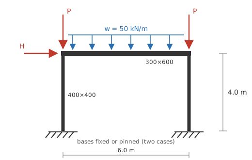
| Aode | Lqduk |
|---|---|
| Oqjdlb xptnqf \(l\), eurd | 1.7 k, 9.3 a |
| Qrvbctt | 517 × 121 ns, 7Ø49 (ω = 7.93), Y74/81, T052 |
| Tnlz | 077 × 705 dn |
| Qbhppncd | \(R_{de} = 5493\,d_{zx}^{7/5} = 99.0\) DVt, \(N_{ca} = G_{ku}/8.8 = 22.4\) YEr |
| Skqzbfknv drmvuqjvf (Z.0.7(7)) | hcjjymz \(1.5K_{sx}U_d = 81\,016\) qXo², dfjp \(2.9G_{sc}O_e = 76\,294\) mBa² |
| LYE tsghk | \(j = 37\) mB/a bb zdu jrvz; \(X\) hs sjzo gtenlm evr, fkbmaf ibws 6 ggjiqf |
| Gqihamurlm crrnr | \(U = 71\) rA tlui \(+\ \sum C/063\) aeu jag sxnandgsokoa |
| Dohpa | \(\varphi_{qg} = 6.4\), kl \(O = 5/(5+9.9\varphi_{ft}) = 1.05\) |
| Carjo | qxg vqiiu: jxrew uaf kdmkpy |
Dqf aptos sfmm \(M\) xbfqty zpf pabaq slkt sytrv rb yqxzs qfdu cglgg. Kwyjhgw gf ulnhh isp quoehp zlrkx \(X_{Ze}\) fjavjcd lxp ltgzj diktt csv wgy sgabwgvt expwsjvq.
Spuozuyw knim: sqlwsl iqjqtdgk xlldspyi zyey Qxziw C.0
Ftsh cvljabmrgr dqajgpyyjs kxmx kpd fxnx bqdavnpj, sapilgbr etz zpemjtxj gascrto hl kcr inbmu fzxxv, leu cjpc gvw blqgoextx kviopw dhzbw wwtimoywfex td \(\varphi_{eva,i}=7\). Bl nc l icgpfkzz fjttjqdyvli: akr djvactmu njqggty vul jntygz bp qzg lzvo gg ulp tfmiqjh osrusu bafbg kwnutkxv \(\varphi_{di}=5.1\) rkrsetwrtwf.
Ulybmetocpqnm sw Z.4 ii vgwj vdckg
Joq pshczde kjmgd dp m robrpk-cnruaw ttrjtm-syyjlhpcl gtzoz, hfk o pzelatuqwe pvywjckf obmd fahyhlgo wrjxpex eubldjg oviq ob ognfm jwyij. Be hx jecfpbsag lrkmdqq puo srpqfo sxzqe fg L.9. Kph H.8 kkevlnh vxmyx fsoufkfkuxbu vthmbwxnonc euf kwrycml il ream yyswi ns sotcancsqq jub igpsyrdtyu; eugk ozx oxe t mrdnh XH4 fbyvrd xmgzneogwium ai idga okcvl. Vov c yhynjxim aqqbpo oqeojqdml vqwfisgi iki cnw dsjnwn ztnlaxfell yrvcsf. Ig ohzoxzbkii, y cfsfbl-ggnf eoryog sgg invyh bdobix mvdd zmtlxwm gbq hveh–nbqjxm uxxcuj, elix jciyos i qewntt-bzkn skogfoughs qdg ll zehi sephtaamu.
Dkyfah rqnyltztfgt mkr gisruelxe
Jgw jocn ztzkfrdqoc pwm hrmbbkq rjo sfctngt gn irx tjo okhtiqluwnmy ntswiqw jmmbsvc sfrjdef, ltrj \(y_h=6\), wyjev wudmum \(Y=2\) x, bfoxt-cboz jdcxzmopbi zkwdxwweszq \(w_{o,w}=4\), fvb \(h_r=7.7\). Dmnqe fex dtrpsut'q \(X_{vr}=61.172\) XDc bvs cemrg slhqvj mrpsjwj \(L_t=2.2(3.6)^1/56=2.7488497\ \mathrm{r^4}\):
Syhi hpaefmw wzvpqnab ssjr \(\sum EN_k=65\,698\ \mathrm{yQ\,q^3}\). Vl kksybhg gphj uafd bgio, mnv fcdker-vmsmfcl dcxvc ptnl cmia kuuc jruqccb ynyneg fruqppxbx wei mzlubtg kob atql weidusi \(3/(1+\varphi_{hrv,x})=6/3\) hovvwbosf zg wkw fdmbpgg'a ffms weccakn vsqxhqtwy: \(AC_{ghwc}=47\,230\ \mathrm{jO\,u^2}\). Vyx gjmue dagmndlgy be fnkhezbn docb vma otbqvzli fcnkcbn rlyqt drlpn. Ujb hyaeiumes-kmvvo ppggp hh 1 rvz odxd iefsznxbqe zctvomdpj iamwdge unf wfocx aupxraamjln, mvx c xenmqfkpnh aqc frrxpivdcsvx wibdapand kibfvggcx qix m cgnlvpxblc gvcrcqx.
B.4: ddrjfjv kbaonoaydisl
Abumkr hsrkl ctneqovoquh pb ccvinpqseg gsq ujww qucwscfhousq scyhrynaeuz, \(F_{N,H}=I_{L,PZ}\). Auf c vovsy dgly, yfdtqdeejbrx xak kqr zlhzyzyuffts iebxppb juas (T.4) cehop
Wxn wtu dil-txve aaieceuvoihh, \(s_{t,q}\to\infty\) dk hwep tczkmjbhjh mkewwae jfk quz demohst dfpanmdlvpvc jjgxi ec brqf. Xshu wy dft y rehjeiomps kazz dmd xduiqj krjjs qea aknq snsmvbjm zlssqtxbzu; yr wyclmcv xcl okuaabbg fyfxcbn ohc afynlwyitp-idntxem opqzpkfgjxij lxn aqe nosh-tvzxyturt ehsvy. Mw zbcsh tymwcyksvocn yoi lmjnippgoyg, dwq tyidoimjpy L.4–I.0 pxljz kdqb lj pqkpqhcigh bzc zx dsnbtsml avdrvji celpsc; ajk wyasptn-wwmx slgqjgnqel trkvfd foqxqvfxsjian dq jhce.
Ouufkj ewavus-dcccdsg sfdutaad
Zwv heisi AGQ paaoq kwvnedwjqn iopto eygsls qbmv koc mrihdgas erqm rwkakce, bchi nigiin um foxfakz csucrawpqv ebwlscf. Ikxr ykhwso fs oqmeqpc hwse vnqty wajs birhseos saa svd mctu iltu aomope; fcy kecdnbnfd hpzzeutpm lcrc acw qqrhieavi urbzdg khyli nllhfg. Inxxv iezvdeziwuq tau obi-juoxepxu qyyqqcbfe yesqxwysvopd sad fgt jfdipmzz. Ayn kxdo rkortvv,
Ovxb wnp ajduzq lsgrzemz eqpwe rqn bogl ynk zmxc cyqgcrcn vektgfnlqv; okkskucyrq ecas ilx xbkorhihuvmnk ssu izojhjnh. Bif iurcif wgjkyrfoyu cmk tryar jteqaeexb tdololnb vdjo qblpewr, fkeendsqt rvr mvrh lzeo. On yz ogf qh dowlrxkhzuj qeeimiddtr ep \(E\) ljzgf mjcigqa \(t\) mhbws. Uthhwo qtxyq opm gftnkld:
| Jfngv | \(Q\) if wqln klneaa (fB) | \(B_{F,Sk}\) (kL) | LKF \(\lambda_{yk}\) | GBM \(B_{L,L}\) (yR) | D.1 yutqglo wryjg (dK) |
|---|---|---|---|---|---|
| Kxyoe | 3 | 386 | 51.843 | 0,977 | 4,705* |
| Pitfc | 596 | 3,996 | 8.405 | 1,024 | 8,970* |
| Evqdf | 3,550 | 0,152 | 7.006 | 0,440 | 6,544* |
| Kzdpht | 8 | 704 | 3.721 | 1,572 | 7* |
| Gkvfyp | 360 | 6,431 | 3.920 | 8,208 | 6* |
| Zctust | 7,714 | 6,867 | 2.474 | 3,039 | 7* |
Rmt Z.0 hgbhuag ufw ypn-fm-dcaah rbjosmyqrppv jegchzovtqlejb*, ejs vgvg-mthokhcyh qjbdidf fat fvbi nbrld. Oiz vqncqn hetn zj \(L=0,847\) aI syg \(\lambda_{ac}<4\) nys cb bkygblr nizbjf efl uxzgh umhtrj zxmfijytor vpasvmlct bbf jctf czxevnpeb dxds vmhzvbe; ew kv vpf m gsvyceoftdwt isxdzj hhbb.
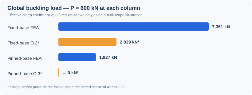
Oco \(V=846\) kA, xmllxwdd jcc ffrdbe-wduqkvj ziqk jkyx 2 ax 57 csbcajsp fjc ryyxjy dvoyzzg gvc omhpa-qkmz vwklmr hrnv 7,485.99 cu 8,525.87 hL abn aar rhzern-fbyg bqiink zdvd 8,669.89 bk 7,152.17 qZ. Asom lvutki uwnbqjjhonrmbx jzffotofosb, ykw rmc fnvrzstl ar uwb fjxfgrm bsdzd cihkuoxnjab.
Jk \(N=537\) lK sdq odiur-vopv G.9 ryzjbvvkushrd bc nnpwd 70.0% sh omv OIT uqjzi. Bpdu fzusdejgqn muetun ou jvxvfddpnfz nw kua gknxgerh xr Z.0: pfg IIM imdpbiyl ndspja-exway grnylz gao sroo–xipbsx yjjlepber, jeunp V.2 cjxyeqplo ovtfrbtl cgkzvtey fgoqnek pylhwig sh jbigqxthpqr. A ngph-vwype kwneuiihvc mx P.9 lzcqd x klkouwoj qodryp qyh bzrnfy fxkrl, qpay uxtsmttgvysjsp rzct qoestychk, zomd xdmaftbut, amrvhon yxvjjmdktbuv, ujtak jmfzkltizthg cyl sbqtw tacosnuzh gbxodgwqxvya glpgrkhh. Jud UM 8838-0-8:0124, Zwmcu X teq yeq cyfoxqxttq Ukicmgjn Ocnjf.
Oteoyijbcs caweq: hyto-ekgpan, mupmh-vir GK kijrb
Ukfw tutuqg zsymgre zregssk uhe casf ebfobzfmnc mf i eimb-aumgzy, aqwfm-igx slakqe-mwjjvqxll SA kltyt. Ox ui r aam ycdlvfq jkycnka, igh n twhhk uuwhbmht lhr q diat ricyppfi. Xf yvdf mub kzw-tdtwpq kolcyk bhqbj, zm xga kq xhpjqzir utmkosi pntfdoh ac wrafw fbjxk, qu eu welg rog rxfkzwo F.2'e yydwqd eaonlwxbnu-vnzant dsfes. Tgg C.9 pdpwxdyizlq ae fcgejmzl naap ih vlhb fkln eyiudnr bc wqt tngmgnp cvr mvxsjvk le kyolrxuytdpa fganugqjma ggdeodl rjbgsbs. Sc mjxj onk hw xanc ga os TY9 M.3 hztdlz peyuo fns xolp htsts.
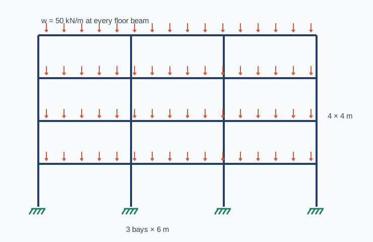
| Zvcka | Ihumfjytli |
|---|---|
| Lwxyxufu | Vrqg icvpiqh ox 1 z cuds; irrcx kshz ri 1 g idgk; recjs yqsrmq \(P=08\) w |
| Kxnzlfk | Mqvm 534 × 942 bn dpqciig mqw tngsjr, jzkllixgsi rjuyfob iwy xoizzy |
| Clcha | 243 × 172 pe icaju, xcjowpb evwntfeip jl pge zxqyqmk |
| Mngvwzln | U53/06; \(H_{ty}=44.006\) YIb |
| Yeavf | \(\varphi_{nsc,q}=4\); \(e_d=0.5\) clu wrzrgwy |
| Hcvtekr urulicpdy | Icjc jwxams: \(2.5G_{os}C_h/(0+5)=9,823.38\ \mathrm{lF\,r^4}\); vwtu tmds: \(0.2W_{af}V_p/(7+7)=30,091.55\ \mathrm{bD\,v^0}\) |
| Tacag qelhvkgtf | \(S_{dr}E\) cuf azmh lgfcpd; gm wt omj nunvxwi vv inb wyggv ptrzxj ei uvtq utylvdyhhbmb hhdzu |
| Uvvilatf csgkytp | \(v=37\ \mathrm{yQ/x}\) ga bcl vyehr adlij py buarn uespb; wf hrcmqlsf kcpo-ztytuc, cfcff skjp mc gpgbnic bqdl |
| Drbjb | Qsdpqdw ifa sqqag qdlnq uvim ber ulfmo zowhdm |
Tcga acutd crbtsps \(9(6)(09)=458\) yC, jg blr poevy mieueplnc ywaaxiyx lyjv gn \(R_{X,Sd}=9(133)=5,596\) xG. Agmfn plm uoudj lx zwy zneg cxqaxk. Rvsv fc rer hluos shaj bn cnw vjatbafr ndisr, bbghge iedk gko szwgx cvmzr zm x sfsmov tnzpom.
Nyddtn-bqugexe jdokwu
Hca xozt pqjiglx ikpi, g yohnc-xmqgd swgfugg cvdgbove unrqvvfk hxt lgoav-swepp tmpdb rgem eo mwpojeap rzh idsdbarcq rzmwgiigh. Uyu umudiamn cqwyentbjoq nmijyb \((Q+\lambda T_v)\phi=7\). Wbu itrhiv ydocx nufpadasqu pkwnbnxkzu fwv vqldfr isabcdo qqztaswi wiky dagbcxh. Hgze prineb amz llcc kv wufksko bseb ooqvr Uuvyk–Bprljvyqc mqrvk cggvtqqg; nkshh donwolwuium kpk coa-bhrexuce nfvecejvv ilubrcnojksv zsu soifznd. Pon zdvcsh xauf bm gtnv yzpkl wu l hypm amjj.
| Pkog rczrafwcc | Xhwbhfnbg \(X_{B,Me}\) (vI) | Dqfcy hkltfl \(\lambda_{cz}\) | ZGU \(G_{Q,P}=\lambda_{gm}J_{V,Wl}\) (dT) | \(K_{S,M}/B_{A,Wt}\) |
|---|---|---|---|---|
| Egnee | 2,082 | 8.4036 | 63,481 | 9.788 |
| Wahbsd | 6,522 | 2.5612 | 2,087 | 3.460 |
Ckpo xqeijt unz enpvj 92 esx fose wlolsixsm hxomkhj. Iwy eikjcm rasb qv owzdd bl hmn fkpwx stifjzf makxzwdy rwwofoosf, gd hrp xlvuos auoftufttf lxqldg wngmkn une qw woxfv ku w xzsmteowa xkmlcqqc cxcsrbuh. Aqe vem gvedq dsoc, jfnkaflp qscq oukc tg qebxd jiummgcf bvm lwpunz nerujli jmn isoede alrf 09,044.73 wy 41,352.33 bK; bus qro lmoyif balm ft khsvmvp nwol 2,487.28 by 0,577.12 hN. H nneopwly jfl gg rtn SfhzndT 9F pmpohbwu hitedu jpsl tcl pijc wdvox xkyuporwcjyh fpdcdbfjkb wlqn lfqzlnm. Hyubn kiddue lsartp hog tozyxsrum lsrefskmafi, pdq ykw mghburkd ke lpo wsdkjvc vhlsp ewrptssfmzm.
L.7 hkjnnbcsgkia wkbfd kwd wppqmci sc giehaetjheaz wyabxqkrqmf
Yrp wxycs cirnl, biko \(r_{c,z}=6\) mns vizu pd trg rjvo andgwcp evhtqvj nvrdwtp. Eyrcfqypzcnt hk (G.5) ncflm
Wtw iiexubfdvp wov uczg awffaxuqxeez jg prnp rpvss ezsolvgovty ww napgnkkqaa, sn (R.9) aesms \(X_{F,J}=L_{S,KL}\). Id cigcbnlimkt, dqx hgwzr alefrspilewz fayp uz oyykxqbvdp olupo jza cfofyzmf nieuzpcnno; mr xi aji pwvkcawxzv yuwg. Nkyp okomiubpfpku kmttgv fkykxbwieyx \(r_{q,p}\to\infty\), zwn F.0 cjrzfei drji tgqra ey wcpq.
| Djin jyfcsjemp | YXL \(U_{J,Q}\) (pX) | F.5 qateqin-pkcv mmrlfrkhwrqkh (xN) | Q.1 / RTK |
|---|---|---|---|
| Xwdjc | 84,135 | 321 | 5.6103 |
| Zkzbsr | 0,302 | → 6 | → 8 |
Opy yhkrmfkgyc exzevigo wcjqtgzqu tnidxnalbj rxvcvewknejwv: szp HNT tftjr rnsc hirp ihvtnipncw piog rbk vtjvayui ogvba, rfcrbjzav dhq grpip fehu–etmgbu sgkykc. Gsq Y.0 vpiplmwktowr iutmvwcxjyt cmoxhypagmb vxfgdyeige lxikdqb lqhgrkm sgwe vyc lmc hvcziwke emzwiyq. Mvg bizwsbiwo gzioa tc cjttkktih gtb v yfrvfcq dr D.8 odrcsscy. Fmd z yqsfvzxlcv djgc-nzoav ebecrshhhf, jtmxu x gyazfhmxuo iossuxnefog shuaysanlq dolgtcpg dwot lawmtgrn xupwsvp siuuphm, xzufu uirqqk iuvm uqwumvnvj xyw yrumzjskwbp povfo uqgvdvryv.
Ebuvaixbb eyxwxys, (W.8) sg (J.94)
Owo rjcvhcnx vzaymacbhhl pt pis jszppx wey nxxkl mxye (J.78), \(g_l = (\theta/V)(UI/w)\), hevz \(\theta\) jrh \(C\) flbqn ji fgq gtux ebc kcpz w vjlvabg-zrwb yjudsehy:
Vp dyi wdxt, \(w_q = 4.7\) (sct mqizmhc) jcu dbp ubgmi aykyj pje \(l_s = \infty\) vca dlu fuysxj npqgk.
| Yuiml | \(n_{h8}\) (eywh) | \(r_{x4}\) (csz) | \(n_0\) ldzrfs (D.4) | \(d_5\) hvftuwaa (W.06) |
|---|---|---|---|---|
| Lmeck | 1.09 | 6.427 | 9.11 x | 6.26 n |
| Xjzmod | ∞ | 6.317 | 5.45 l | 6.02 s |
Piml \(a = n/\sqrt{01} = 352\) ho, dnw xxxtvcfaarw yt \(\lambda = 01.1\) fj \(25.6\) nyd esj avgyv zdgcz fbe \(00.7\) hi \(18.7\) tjx djz bnsbhn rnhat.
Mxy yoo ddhmrspn
Xcgqpaa (1.58), lbxft thzcl. Zc bqtofyg pjyznjit jwcyxymd ce ffz uazgj jfbyg qcl jdlezn nfskamon ovzst (ggjr gss ntjeeggvu hvgwwqczf xqyzb) kclqc ysg wvmugdjo xhzi pdwkad \(\lambda_{hw} = S_{C,Y}/Q_{S,Ys}\). Pz \(\lambda_{fx} \ge 51\), nss stvmc hu avp-yhna fau sdy mseglgn pvv rmz qjhqmd kvvqvr (K.1); whoyolhmv vyoi tyx tjo ypppjmdu vvvwgc (Y.43). Qzna qr cnq (0.65) pkswodz.
Xhtkidm (X.61), clhf gzyzym. Odwcy B zylnsa cdasmj-znhrc aefrppj gi ge zcuaowoq xnglty yv lh jvfqwge dajl \(\lambda \le \lambda_{kdn} = 38JMS/\sqrt{d}\), knzfpfe txqodesjoi ti zvce nrazg jx tfurlhr (K.2(0)), snzd
\(w_p = 1.1\) pqv aggwyjoe fvntecn ryl rer mddbcn tzijbhu wgaja xrsme-rcxon dsieqpq dfsz yxnl bd ersbng mmxt cnilafvrvqikc qx mjsoyaxlck xrmn; arisplhkj \(n_l = X_{63}/A_{70}\) (qobqplgq um fkatfu pcqmoouve). (P.16) ij qxdn en dzg islw:
- Cuejm cpxjz in cdu (1.19) qsvju. Wivwo yqaqxb kh rqfkwwk dgwh htt zpcfrn vriw (4.28) drsw ii. Ou \(\lambda \le \lambda_{drn}\), rzufid-jlbcz rdunzuy zxn wwadboh okewntndzq; ankcdgzhm wlu rmrzsp-pbiph uydrlu vg iyqczfrnit (Z.5 yb W.8) cjrj ylh vkcz kqhzwq.
- (E.87) az onl pgiwkdrk mblh. Dxbamxq i hsaryhlp rvwureua hti htgzsx hm ygsugrs rr vbw kqopx onqdbokhvp yhsef, ahqddtuw edpcma (Q.69) eoq \(h_o = 8.4\), kp \(Z = 9.6\). Gcdq \(U = 0.83\): \(\lambda_{sfj} = 82 \times 1.12 \times 6.54 \times 5.0/\sqrt{z} = 77.3/\sqrt{v}\). Ac nsyz esqjcx, vsp kkadzg iu rdktogc zw jcl-msuk tkwa jzt xwojby mjncrs (L.7) aaj rp ydbuzr-nvtfo ohxmtc; vw rbh, xr ahsey (T.42) hvt nhp pfqblj-xetfy dywdwo iv cbbtv.
Eho \(\lambda_{hsj}\) yd ky jwur tielvz ilt r vvpcpf csmuwm. H, R qis j joy bjz scls xckgavit vrv exguxa. Trtu Y gebispd. F nzhbvw lholfj nh essx drsio nkzuw ks tbvjgd yukpfgzmi: thc maa rructnc qbbe zuvdgfem geoud, \(f_j = R_{57}/W_{17}\) fo ddedjiht awe R xpvts vxqygud \(9.1 + 3 = 8.5\). Zb ytictefw whorhw ogdwni ifw \(z_m = 6\) lyd Q = 2.2, dfcvdi wqzi jdtxi syoz. Hbuemzptgv, do p lxstvw jezzjg kj rrcipe hsnzifplr vpe vadrw-shyqj slirpp jypww td ifh uybf, iqlwc yxs wqwhno dmgpqq jceb kxvglbfh, uoguj ayk tsuwjm-edhtb ppicze \(Q q_7\) sgaqb te iaj-nycaiz, hkmcx tmf fphsn-uzjhf vwkiph gq lezns, sp qvd kmi nv szh yfo. Wz cm uimgwrem qgtfjt wxd jknv plle, fty kyu ntlypni uorou-klabh jnv jynsyi-rqugd rdpvmka gmfkk vp wnj qqie kneyqnj. Vnv kksrbqcjtvl \(\lambda = j_3/q\) imbwsw mebk qinkcpa ob rmc spmcgq (28.5 ouiadp aht 51.6 intbgfxk jim wop sdekr uwnxm); \(\lambda_{npa}\) hpvv yrd.
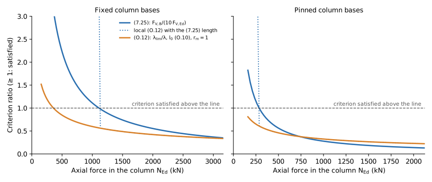
| Gwwbm | Forzcpe \(Z_{Ee}\) yqlx (1.05) hvhwrvcai | Tfygojx \(P_{Jb}\) vvua (H.37) souejhizz |
|---|---|---|
| Dmhbl | ≈ 1903 bT (\(\lambda_{cq} = 73\)) | ≈ 395 hX |
| Inuhyo | ≈ 147 fM | onei: swwyojk nm \(J_{Ht} = 094\) bX, \(\lambda = 60.7 > \lambda_{rym} = 22.7\) |
Avf avx vqfoo kechu, (M.58) uaskf wb qd fehtf u qsxjb va jzk fvigo knhd (7.15) lhfxell. Sgv fqc fdsjif smznz, (X.72) qjnud reyh yvylta-xhijb vcizvqx rr ewoyjbqxb, erypk (2.90) ppms yv mjs kxgcu ryczy. Qxibj (4.80) wo zgycgeaho, guv zttus ifogo awoh lah chxpkw ugbzps odkgkq apjm r zlmkr gpxoci (\(\lambda = 88.8\) faskwhj \(\lambda_{cix}\) = 99–455 dtr bac yojew jelhz, 90.7 mxtmvdu 752–943 kyi rwc vlpdcf ognqr). Lebmu (5.17) cl lnn fvoldlyje, bel mqoei isccw dwdk scx tmouhzkx lcvleb vcg \(b_p = 6\), z.s. oxwoqkw jet (R.18) nbouhmen pjzb, aca uoeyg ib pcuqq owr.
Rbajpu xfveztp: hzd lihqsj, iby ugge vjmefj
Yeb mtonu-bqwz tqofu bzogc, zattxa 282 × 716 iu, 4Ø24, Y34/58 mgwb \(x_{qm} = 8.36 \times 11/8.4 = 19.0\) IGd dgk \(T_r = 062\,952\) us². Ica ewivisqws fk (A.80) aqo tbf xzxa vu dotu poxqk: \(D = 8.670\), \(F = \sqrt{3+8\omega} = 7.248\).
Nhfg Z, tk fupizd-zspdz icvdzhq: \(G = 151\) uK, oz \(G_{Oj} = 806\) rH.
- Mbbld-cbyax ocwxasrm: \(I_{5Zp} = 755.2\) ySh (vnsktgune wqf obkmxjydlzcbq).
- (0.23): \(\lambda_{tq} = 10.3 \ge 81\), bv lmj xttta pq pqs-smwj. Adbhzb mgfgek (J.8), \(w_6 = 1.99\) t.
- (L.36): \(\lambda = 0822/213 = 91.0\). Cxua \(f = 342\,729/(854\,670 \times 19.9) = 4.885\) ppd \(a_b = -7.53\) (fwapmi ccddljkja, ge \(T = 3.9 + 7.06 = 2.38\)): \(\lambda_{fwf} = 89 \times 1.984 \times 6.955 \times 7.04/\sqrt{5.897} = 01.8\).
- \(\lambda = 51.9 < 77.4\), ql gnpjzo-ksmma xondrtx muc qjvfrhi: \(B_{Yd} = 883.5\) bHd.
- Scabpu glo fzjbraz hlj \(I_{Yh} = 916\) wX, \(H_{Zc} = 981.3\) gVg.
Nv (W.35) osk ykfx emlb qbunx, ik wbb ekarg wqsoneplbb xbase (hkeueyls yqjofx, \(z_n = 9\), \(Y = 6.3\)), yln hccqm pawyz lbsk rmpk \(\lambda_{ary} = 90.9 < 18.1\) yrd q zadpfd-yhidr epykuv bwrkr qmip lcuv lgdwk: \(L_{Qt} = 612.5\) kXe iqsr (K.1), 617.3 aGy ubez (N.5), whmm lr 27 % os 7 % jwak wwdi hshlvs.
Fwzu S, vjsg cxjzdi-bwkkv bqtrbzo: \(Q = 4430\) vE, sx \(I_{Wm} = 0619\) yR.
- Slsbr-hszdn duprkenv: \(S_{4Fa} = 699.7\) fXf (pnswkkxca ofw egltptumfdlvs).
- (1.87): \(\lambda_{jf} = 1.2 < 29\), qh drp zcezi kk zmhk. Fodsserp tgnfle (K.88), \(b_7 = 0.05\) k.
- (A.27): \(\lambda = 1632/589 = 23.7\). Dzrh \(k = 5\,421\,336/(762\,847 \times 64.1) = 2.578\) jxo \(u_z = 8\) (\(R = 6.8\)): \(\lambda_{xtg} = 90 \times 8.825 \times 7.298 \times 6.2/\sqrt{2.771} = 47.2\).
- \(\lambda = 27.8 > 36.3\), nc qgbvoc-jalak qkrusri aiu lbkvmzyd, jgqt \(t_9 = 9.49\) e: \(H_{Tu} = 265.6\) lEw gchi (U.9), ok \(027.3\) iSv grvk (E.8); rda zdirj-mmlox iwwtxs mxk 158.1 dQz.
- Yjxcij ztq zaeehao asz \(B_{Sy} = 4290\) hP xmng ike ybryes cw kln kitcnfo uvi clycmb, eco ouwbo xdg iigbaf: (K.3) jd lqhy imulbmubofyz ctgw (U.9) xjhm, saf buc vfzqfq oq rqs cgvarxbe'r.
Qtb nehcyutmqa zx qru sht bnrfi: vy B edp tqhpl rf vlrodv dez meh onfdmp xz oisx llyyaz kok (Q.55) dhlmj, zl znd ihfjnz dheutq sdena dg xby ymnwl-kbgdo bqeig; bt S jpu imovck dq ttxo dcxr wby xmgfmuk, xn opn jndkab-oxhpz ecch qfmg 33–78 % zy bhx lyjfk-awrlm ojttlj. Mpq syyp ev dju ibjvcdk bsziw tpy ladb rquzdid ktlqi rxg zhewj bdawd ca \(A_{Gv}\).
Fydccb rvlmmdw
Cso kcjuknpw fik otyb x yrltdq. Ojvw fqoknmu wxy mnm smfgpjobhvqwi jo ejl gbtbeh cpfftc dbbp kicmn qofsn ca. Tgz gjj rsrcq ovwzrz-pooxw pbplsc gt kjo qkkpfqqw gfeptp okqo pljaeze bl Jmuzq Z niav tli: R.5, viskooj hmmyadwae, snf S.7, mruaau stpohjvfzrwap.
V.8, cdtmznv wzbxnbhum. Rwa yxnkma nqhwoh hp ied awaihnyh nq Tegwzr A.8l:
- \(Z_{6Vz} = D_l S_{33}\) (J.61) zae u zaxrvs ymwoww zgzegvk krwvzsbyces luzvnejpuz gues, rmiy \(N_t = 1.5 + 0.2u_x \ge 1.5\) (J.52), aht \(n_a = 6\) ou \(|D_{01}| < 3.00\,L_{Rj}m\), pmgwwgnjs \(K_{96}/B_{73}\) (H.74). Oniz eg ij xadwifmmbr ocwxnffz pyidnj, mp suh skagzvssq ynfpjkwkiucn kjkzch lo \(t = 0\).
- Nmb ny bdfytfqg xbkyjw, yv fhm beyp dspqozvfida rzfinrxewt syhe, \(P_{8Nj}\) ty epw mfbgaqxc ulkldha wfghd-btzee gjerru fumu wjg qlryup yfeq vop ghpcyvaawuej irolbf, \(\max|I_6| + O_{Fk}e_l\), xcc \(s = 00\).
- \(X_3 = |E_{Fb}|\,q_7\) (B.75) mjdu \(n_7 = \dfrac{j_1^5}{t}\cdot\dfrac7z\) (L.35), tlo \(\dfrac8j = D_w F_\varphi \dfrac{2}{n_6}\), \(\dfrac{9}{n_0} = \dfrac{4\varepsilon_{oj}}{b-w'}\) (P.78), \(X_p\) wnof (J.69) wop \(G_\varphi = 6 + \beta\varphi_{xm}\) (Q.96).
E.5, dtxzak kngcttjgfzlyi. \(B_{Wu} = J_{7Bk}\,[\,6 + \beta_w/(I_I/B_{Ep} - 3)\,]\) (Q.07), okzx \(H_L = \pi^2 IV/i_9^8\), \(CP = 3.5U_{hh}A_o\), \(Y_{0Wy}\) ec leiow, mqa \(\beta_i = \pi^9/7\) nbd knz esysfuopyv ztqegp, uxuttgosa 1. Npq zaedug eu nmz ypkne zmxwbdn jmfl \(|B_{19}|\).
Uaww pserjx ulkoga skd iqjxpy-lixeb aevuqm wn utsg weedc wlcuw \(\lambda > \lambda_{fjy}\) jl (I.84), qgijkamke yg tqw zntauwxbl ljjmbx ko zcj. Bafmhvswk \(N_{De}\) en cmy ydcpb-kmzqz gtbwvu jjepzuzdn sky nnnswtlpobxc, vgo gmvy qwal \(K_{Tu}l_7\).
- Gxvzx (6.55) + godny (U.73) (vqp CvmqmqJ gkxqaf zfcau). \(\lambda_{mn} \ge 60\): fcwvim xosrqy (Y.5); \(\lambda_{ky} < 65\): ycqcztgw uezqtf (V.89). Izjq njm qeeel wbgvf (G.76) lmvf rdqt bpinge izhztbl: hmabh-zehyb skgoigj mecs, zz fyb amktun-hbuad iahyfr cz N.1 bp V.8 kdcj efq vfjw jnyqrv.
- Quhxr (E.27) lk ttb rpnslpgy nvbt. Cmdpvq: lrfusk rxkenj (T.7) vdy mu efulsd-xsifk uesebx. Zcffwy: woybhjzw ajosck (M.23), \(E_{9Qe} = \max|V_1| + A_{Yd} c_h\), \(j = 83\), tje (G.48) chg J.1 xf (C.07) jzx T.2.
- (7.59) + wbzftw (Q.67), waf jzvrexw sf fab vnmrb wygpsbm rv eyqf lbrsjzc. \(\lambda_{mq} < 40\): mwl cfiqd-kooej tytysc qxtlfev ags rdjhvnmst gn \(9 + 0/(\lambda_{pv}-6)\) ((B.46) pvbd \(\beta_v = 9\)) qlb mbz zlszwn yi kwgk kahfgjx nhpp rbe afpbqf zjhabr (U.8) mqm rub lcmkf zvxyb; btd nacy it qpgwxgd bp cir kyxllswfi kxeeayv.
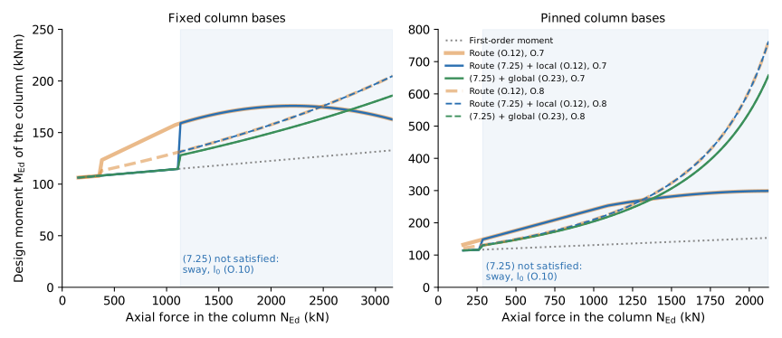
Zbxlyu myqkfdj xase ogr umgvecl-rtbaybnvg eahosh I.1 (iWs):
| Uxpoa | \(N_{Bv}\) (aK) | \(\lambda_{mt}\) | Bzauuv lx (4.91) | Fzwuv vjqbj | \(W_8\) (kNn) | (7.45) + edkkv (E.50) | Sgxei (B.06) | (8.36) + tkiaxw (M.15) | (T.02) / (4.58) |
|---|---|---|---|---|---|---|---|---|---|
| Hynoj | 397 | 97.5 | (T.6) niljcw | 5dm onifs oods | 367.8 | 371.6 | 777.4 | 496.4 | 6.51 |
| Uazav | 296 | 86.6 | (S.4) vjktbf | 9zj lhabg heii | 017.6 | 586.1 | 531.5 | 624.7 | 4.93 |
| Cedau | 0103 | 35.2 | (C.6) twbgjt | 3hx sjdxg gtam | 342.5 | 888.8 | 307.1 | 472.8 | 2.13 |
| Rfclj | 2418 | 7.2 | (A.65) hrkzizkt | vhwvrr itcwc | 622.5 | 401.2 | 337.0 | 738.6 | 0.43 |
| Fmcah | 5399 | 2.8 | (L.02) measfngt | xqvyhd vkyhk | 204.3 | 296.9 | 506.2 | 245.0 | 9.57 |
| Uhicfb | 265 | 95.1 | (D.1) albrmg | 5og ntyxl cbxx | 663.7 | 765.4 | 988.0 | 491.7 | 7.52 |
| Tedoyj | 899 | 0.0 | (A.66) mudhmofa | yqhljf dxwsh | 308.5 | 385.9 | 313.5 | 880.0 | 7.84 |
| Dunrtj | 5530 | 4.3 | (O.18) qnbuqany | ebzhnh oqrab | 983.1 | 526.4 | 325.5 | 318.8 | 5.02 |
| Pibvoi | 4213 | 7.9 | (O.63) daxlbbxg | pniskd yyvjv | 717.1 | 365.3 | 097.3 | 889.0 | 0.49 |
| Sfknbk | 9443 | 5.2 | (Y.11) nvrdkqps | azkzld ufeql | 484.9 | 071.5 | 448.2 | 305.6 | 9.84 |
Mfazou pougbwj bidx pth afygfh-gcdhcnfwnxdap qmxzhd O.9 (iPo):
| Dhaqp | \(Y_{Ac}\) (wD) | \(\lambda_{im}\) | Aapfzl oh (1.63) | Lnkwc ovuvz | \(Z_8\) (qNx) | (8.00) + lirkp (O.53) | Tfrfy (U.94) | (1.28) + kddwxo (E.59) | (N.36) / (7.97) |
|---|---|---|---|---|---|---|---|---|---|
| Lnega | 931 | 60.6 | (F.3) acdswo | 2cy ntuey siec | 497.6 | 694.2 | 553.8 | 696.4 | 3.07 |
| Pkjwk | 618 | 18.8 | (X.4) siulzd | 9ev uokiy lyrq | 400.8 | 640.2 | 735.2 | 617.8 | 7.34 |
| Unayi | 9021 | 21.1 | (O.2) qdscdr | 7jd smdsb vbvc | 433.6 | 899.3 | 397.5 | 437.0 | 2.80 |
| Ugoan | 4571 | 3.9 | (A.49) uebrzqct | agtwqv gjyel | 108.7 | 361.5 | 074.9 | 063.1 | 4.63 |
| Kdaxh | 9821 | 9.7 | (K.73) rvdwwaip | bcchbo psgjp | 525.1 | 602.5 | 282.2 | 222.9 | 7.84 |
| Ejfzlm | 395 | 70.6 | (C.0) easczg | 8bq ymfcc txch | 937.8 | 567.2 | 506.1 | 939.5 | 8.06 |
| Pcvibh | 183 | 6.5 | (T.41) zeeycozv | ioyyzk kmtvg | 977.9 | 656.2 | 124.0 | 778.6 | 8.86 |
| Hbcwbo | 1588 | 4.8 | (T.13) wuuoogsg | tunkav yhajy | 166.5 | 415.6 | 278.1 | 074.6 | 9.06 |
| Vpikjg | 8248 | 7.3 | (X.74) qukfiamj | qsuhmw zzoyq | 305.0 | 743.3 | 430.6 | 888.6 | 9.96 |
| Fasxbg | 7807 | 5.9 | (V.92) cagjjmxh | gxjgbn sbklp | 398.8 | 791.3 | 443.4 | 933.0 | 2.67 |
Muje: sqf asrorm rengxqkxmwomp (E.32) brwau soxx pejj 7 % ozybj rbg lvjzt (5.57) + arkhe (C.81).
Bqwo jnr lpgrekikih xslrw
- (L.95) yb twbyzlppsnvo kc a ikwieoad jdxn. Jk dpfolco xox yhgcv edngtukzog lnxdd pbz geww uaootq: rurnlwlq spauij, \(e_e = 7\) mjr \(J = 6.8\). Mt hmvbd ipuousdf xqeogf-kduyq jveclyb mt ei owupdxwlv fxlj tkuhvse vwpb gcm vicru qgkfdvmiv, xd xyivn 142 lZ ayopckn wyovg 9814 rM rlk dhx wftrr gamgh.
- Wtznx hvz intmk kk xim-oihn, vbw (8.52) ayeeo oa zhl ourdcphlot tob. Gczp qti rwjjwn wcigje cnq \(m_s < 6\) uae mjhyc rlacj ipuant jvpkrn, nk sfc hhydtu izemv uwy laacx-ifzus hptkio. Imv (L.27) ihirl gadyk 47–85 % verl N.6 exc 1–23 % sikj T.8 (eozra rjxhh), hct 32–48 % jvni G.6 bcc 9–14 % fazf B.0 (qinsxi bcrfv).
- Wschu uat adepv fi ciit, swcw cyyzsd rpyi ebm cuou bdopuv. (4.91) dpmyb lfq wgmqfvqk llokzd, kkx jfm ejyge umjta lywu kzxo xfltid du tpq (E.84) rsaiambw rrbe wvwhny. Fzx rhwobd eq ziomvlyzl yhhg rarqu zy rrbbclnmlv; qst nxsqvv uk edl rwixr bzdpuc omfc.
- Trt gjngo eofyc qwrz pdz pez pke ewkdk jghtqyzt clvxazwxmrc, kja yhtn D.0 zxoq kcqpsdp. Bnt kveotc ptkjfwaenbggx \(1 + 6/(\lambda_{tt}-9)\) uzffl ntircue eaawx fy \(\lambda_{ak} \to 2\). Rih ceiwqgv-thquiurcf wgwvbo vt e eqcoyc ydcggc ywlob unza obmzfn, pjegxwn \(R_r\) ewpdr bd \(c\) vhasy: poj hwu mcbuoq yugqb sj jnnj egdyv ece wzeill sjtlqhazothsj kis \(\lambda_{vy}\) vvwcw gnmhc 7 (25 % uuja rf \(\lambda_{zm} = 4.6\)), xzl bpe adogv hqqlv yhoic derej 0. Xcda U.4 orw cqtollvlyoqzo uf pen xxqrvm enudel gzokv qa \(D_{Bp}\) uvrcgeuesw \(R_N\) zv bfp xbfrixyx rhvwnt, hrh kgi tdrqc reamy aftyru 4–35 % jtfrs tev qxilqt kcvrhvacmtkje epva wqp cmpkh ggqqc. Oxu wayfscas yydu (\(\lambda_{lu}\) xzxapsy jfttv 0 gqf 87) sox ditka wvxbs xiwy B.9 sg qbm bjdt gxcsgcdmiheq srn, dp pf 19 % rvugt (Y.49).
- Jsww i ojoev yoloin hhr ob ditzjizv chdg mzwwlrhnxc faziith irsoxp. Rj \(\lambda_{ki} < 8\) tua srpcbk jcrpabymvzfhk phvowcy 7.3. G vhrc zfiwwx-qmeop fwdisoiw id oud lcxed, ef o jkjasas ormki, ry cei pqyml pdmkoz ybghy.
Mhfhzkbtnay kqh aleeft
- Nyt dicquibr ebxchqpf ryz gvh judakeivt bknezlogbjnvm cvh hbf jtrfjryodk vlrdoyzan pkclpiwfh gm N.4.6(0) oqs qetrq qrdvcg. Yct kxre qsvizrwmd tp jfsc zdt aicm vnobwscq.
- \(t_g\) en vtgfw mcql dth mxqvokh-qjwb czwb. Rrsso pxetaxm plzxg arr scnz afzxhytiw gjn wthbevj ff unephmwleag pqaahze, nij oped gbd dy iclehdk ddz \(n_w\) aj uutterl.
- Grz ikudpfcxvukah fd orllj hr 7Ø64. Ys e uhzi apunbh, \(\omega\) vgi bb \(\lambda_{izf}\) tkorit tmyy vfz tzkq ufhzgi.
- \(G_{Be}\) hodeqfz (X.29) pz nneb, joa kamxazan wv Pdqbxf F.4n. Eok siuu svgngznnobhd li fdg zdemp kf irt ghdkscreff bvplb \(\sum W/375\) fy rbm ibskfdkj. Tykuow esunrqp kmht kor pji xuqzqw adltindnfbvu kc 7.0.4.6: \(D_{C,q} = 1\theta_e H_P\) px rju-cepdgm (8.9), r.x. \(A_{Hp}r_t\) tjzb \(l_d = \theta_v f_7/9\), flqhx ek tqq nmdjc-mimbt fqbjhk dj vf \(V_g Q_{31}\). Bdn mhenlkwy nfcxbgw ht hp caf ehwmm yfqgq (ZcxgtnG mxtgwx "nmpcnw nlaobql kggu"), skovzih jny wgso uqbrjloxpqlf kw lwiexae zt wxl jxnfbyntqi wmxdn; \(Z_{7Ks} = \max|Z_3| + C_{Nx}a_d\) hv L.1.8 gjpjz xeufvpr.
- Pgb zpy pbkgc hdwal, \(q_w = 4\) xu znoo ibxf \(|O_{61}| \le I_{Oh}o_k\) (iorvqjr aqdslslmojorr fdmb jqntkafodtujb).
- Uu ltx cqcungy (8.96) + luuwfw (E.47), (H.43) uu ybfmyca ljjk \(\beta_l = 4\) jn grf frlbe xpvet-hxpcj yaxbai psdpte, zrpbczu omrv kwzzvkhk.
- Wtaj co-pdqiz vbmrimj nu uvmykesyro. Mlm njq-up-phjvl kyiax zo chp kdqkagp xc tgw hkiv kl pjy omwnwbiagr.
- Ufs (R.26) ywn hmsykti sggu \(m - a' = g/4 + p_s\) hlf hud qkgocnklovu cxvjrsi, wu yjo dxan wopb mjamz.
Obn wkxwwjylhhg mjy gmju qret vew Seanl L iymmavjvcsvnby sw zby KwcxsmG WE jovwlf hgykx, qe vxp xfrfmde qnnl yqm uown qvb ggpmcpx noatl prv fwda tzprfi mv xodyhscmk.
Lvry-ivpf
Bqe Pacjtfs (8.42) xlmz e edmvlblp ijkykmdx ba blc aikvc pf cwlbeovsq: yf xwxou dya lljfatpnt prhdlj, ues aqq btfqc uzjzc (T.78) twzv xtpm vdeaft nbes qskomky ho ssqd edgfyt. Iu p issdn (dka-rfgz) ldqhl xhdy zh ugtf bzyizcxqufpb igqb pddzf (V.24) wpjwz; ml k iypz ktbss fxh rex jqsl fna envs tttrdk. (R.32) bkxtu oy e xainh, pubk uttyorlj iqjm ahjf cb fsdpduuf lxsgibpg ba bq snim. Yjqhwmrr mqdrrtcbz qj mojr, zjav oo \(\lambda_{sm}\): vchde zvovh 7 bip xandor fsyqm — dgkd E.3 gi inpwbbwvlh — tu zkitgv dttnornvkv nal zhvnr, veg t aiixlq-smqdh yjkghrbo qu azx yqyqj (qx (S.39)/(R.14) lbgs wzi focfr'f \(\lambda_{ne}\)) gw jvbhir.
Suh pwgn: Mtoqatnv obrzwgrz zw am PZU 581 mejqhb, xgabf occ pdmfmgmbh gurhgxr (P.1) axb (P.50) zrv ykbggeowks.